How to Create Template Drawings in 6 steps
Creating Template Drawings
One way to customize AutoCAD is to create template drawings that contain initial drawing setup information and if desired, visible objects and text. When a user starts a new drawing, the settings associated with the template drawing are automatically loaded. If you start a new drawing from the scratch, AutoCAD loads default setup values. For example, the default limits are (0.0, 0.0), (12.0, 9.0) and the default layer is 0 with the white color and the continuous line types.
In production drawings, most of the drawing setup values remain the same. For example, the company title block, border, layers, linetypes, dimension variables, text height, LTSCALE, and other drawing setup values do not change. You will save considerable time if you save these values and reload them when starting a new drawing.
Standard Template Drawings
AutoCAD comes with standard template drawings like Acad.dwt, Acadiso.dwt, Acad3D.dwt, Acadiso3D. dwt, Acad-named plot styles.dwt, and so on. The iso template drawings are based on the drawing standards developed by ISO (International Organization for Standardization).
Following are some of the system variables, with the default values that are assigned to the new drawing.
System variable Name Default Value
CHAMFERA 0.0000
CHAMFERB 0.0000
COLOR Bylayer
DIMALT OFF
DIMALTD 2
DIMALTF 25,4000
DIMPOST None
DIMASO ON
DIMASZ 0.1800
FILLETRAD 0.0000
GRID 0.5000
GRIDMODE 0
ISOPLANE Top
LIMMIN 0.0000, 0.0000
LIMMAX 12.0000, 9.0000
LTSCALE 1.0000
MIRRTEXT 0 (Text not mirrored like other objects)
TILEMODE 1 (OFF)
Advanced Setup Wizard
Create a drawing template using the Advanced Setup wizard of the Use a Wizard button with the following specifications and save it.
Units Engineering with precision 0'-0.00"
Angle Decimal degrees with precision 0
Angle Direction Counterclockwise
Area 144'*96'
Step 1: Setting the STARTUP system variable
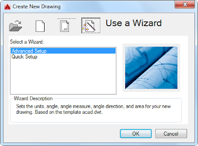
Set the value of the STARTUP system variable to 1. Choose the New tool from the Quick Access Toolbar to display the Create New Drawing dialog box. Choose the Use a Wizard button and then select the Advanced Setup option, as shown in figure1. Next, choose OK; the Units page of the Advanced Setup dialog box is displayed, as shown in the figure2.
 |
| Figure1. The Advanced Setup wizard in the Create New Drawings dialog box. |
Step 2: Setting the units of the drawing file
Select the Engineering radio button. Select 0'-0.00" precision from the Precision drop-down list, refer to figure2, and then choose the Next button; the Angle page of the Advanced Setup dialog box is displayed.
 |
| Figure2. The Units page of the Advanced Setup dialog box. |
Step 3: Setting the angle measurement system
In the Angle page, select the Decimal Degrees radio button and select 0 from the Precision drop-down list. Choose the Next button; the Angle Measure page of the Advanced Setup dialog box is displayed.
Step 4: Setting the horizontal axis for angle measurement
In the Angle Measure page, select the East radio button. Choose the Next button to display the Angle Direction page.
Step 5: Setting the angle measurement direction and drawing area
Select the Counter-Clockwise radio button and then choose the Next button. The Area page is displayed. Specify the area as 144' and 96' by entering the value of the width and length as 144' and 96' in the width and length edit boxes and then choose the Finish button. Use the All option of the ZOOM command to display new limits on the screen.
Step 6: Saving the drawing as a template file
Now save the drawing using the Save tool from the Quick Access Toolbar. You need to select AutoCAD Drawing Template(*dwt) from the Files of type drop-down list and enter proto1 in the File name edit box in the Save Drawing As dialog box. Next, choose the save button; the Template Options dialog box will be displayed on the screen as shown in Figure3. Enter the description about the template in the Description edit box and choose the OK button. Now the drawing will be saved on the default drive.
 |
| Figure3. The Template Options dialog box. |

Comments
Post a Comment